19
Maxim Integrated
MAX19792
500MHz to 4000MHz Dual Analog Voltage Variable
Attenuator with On-Chip 10-Bit SPI-Controlled DAC
Table 4. Attenuator-Mode Control Logic State
Table 5. Step-Mode Logic State (MODE = 1)
*Continued UP or DWN stepping results in saturation (no code wrapping).
Table 6. REF_SEL Logic State
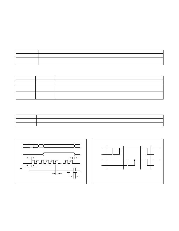
SPI Interface Programming
Figure 2. SPI Timing Diagram
Figure 3. UP/DWN Control Diagram (MODE = 1)
MODE PIN
ATTENUATOR
0
SPI-mode control (the DAC code is located in register 0).
1
Step-mode control using the UP and DWN pins (the step-up code is located in register 1 and the step-down
code is located in register 2).
UP
DWN
ATTENUATOR
Logic 0
Logic 0
Reset the DAC for the minimum attenuation state (DAC code = 0000000000).
Logic 0 pulse
Logic 1
Increase the DAC code* by the amount located in register 1.
UP is pulsed from high to low to high (see Figure 3).
Logic 1
Logic 0 pulse
Decrease the DAC code* by amount located in register 2.
DWN is pulsed from high to low to high (see Figure 3).
REF_SEL
DAC REFERENCE
0
Uses an on-chip DAC reference.
1
User provides off-chip DAC reference voltage on REF_IN pin.
R/W A1 A0
D[9:0] TO REGISTER 0, 1, 2, 3
CS
CLK
DIN
D[9:0] FROM REGISTER 0, 1, 2, 3
DOUT
t
CS
HIGH-
IMPEDANCE
HIGH-
IMPEDANCE
t
CW
t
ES
t
EW
t
CH
t
EWS
UP
1
1
0
0
DWN
NO DAC
CODE CHANGE
DAC CODE
INCREASED
BY UP STEP
DAC CODE
DECREASED
BY DWN STEP
DAC CODE
RESET TO
ALL 0's
发布紧急采购,3分钟左右您将得到回复。
相关PDF资料
MAX19794ETX+
ATTENUATR 46DB 50OHM 4GHZ 36TQFN
MAX2365ETM+T
IC TRANSMITTER QUAD 48TQFN-EP
MAX2369EGM+TD
IC TRANSMITTER QUAD 48QFN-EP
MAX2850ITK+
TRANSMITTER MIMO 5GHZ 4CH 68TQFN
MAX7057ASE+T
IC TRANSMITTER ASK/FSK 16-SOIC
MBA-2060
ANTENNA METROLOGY BICONICAL
MC33493ADTBER2
IC RF TRANSMITTER UHF 14-TSSOP
MDEV-916-ES
KIT MASTER DEVELOP 916MHZ ES SRS
相关代理商/技术参数
MAX19792ETX+T
功能描述:衰减器 -IC 500MHz to 3000MHz Attenuator RoHS:否 制造商:Skyworks Solutions, Inc. 最大衰减:18 dB 容差: 阻抗: 功率额定值:30 dBm 安装风格:SMD/SMT 工作温度范围:- 40 C to + 85 C
MAX19793ETX+
功能描述:衰减器 -IC 2000MHz to 5000MHz Attenuator RoHS:否 制造商:Skyworks Solutions, Inc. 最大衰减:18 dB 容差: 阻抗: 功率额定值:30 dBm 安装风格:SMD/SMT 工作温度范围:- 40 C to + 85 C
MAX19793ETX+T
功能描述:衰减器 -IC 2000MHz to 5000MHz Attenuator
RoHS:否 制造商:Skyworks Solutions, Inc. 最大衰减:18 dB 容差: 阻抗: 功率额定值:30 dBm 安装风格:SMD/SMT 工作温度范围:- 40 C to + 85 C
MAX19794ETX+
功能描述:衰减器 -IC 10MHz to 500MHz Attenuator RoHS:否 制造商:Skyworks Solutions, Inc. 最大衰减:18 dB 容差: 阻抗: 功率额定值:30 dBm 安装风格:SMD/SMT 工作温度范围:- 40 C to + 85 C
MAX19794ETX+T
功能描述:衰减器 -IC 10MHz to 500MHz Attenuator RoHS:否 制造商:Skyworks Solutions, Inc. 最大衰减:18 dB 容差: 阻抗: 功率额定值:30 dBm 安装风格:SMD/SMT 工作温度范围:- 40 C to + 85 C
MAX1979ETM
功能描述:电压模式 PWM 控制器 RoHS:否 制造商:Texas Instruments 输出端数量:1 拓扑结构:Buck 输出电压:34 V 输出电流: 开关频率: 工作电源电压:4.5 V to 5.5 V 电源电流:600 uA 最大工作温度:+ 125 C 最小工作温度:- 40 C 封装 / 箱体:WSON-8 封装:Reel
MAX1979ETM+
功能描述:电压模式 PWM 控制器 Integrated Temp Ctlr for Peltier Modules RoHS:否 制造商:Texas Instruments 输出端数量:1 拓扑结构:Buck 输出电压:34 V 输出电流: 开关频率: 工作电源电压:4.5 V to 5.5 V 电源电流:600 uA 最大工作温度:+ 125 C 最小工作温度:- 40 C 封装 / 箱体:WSON-8 封装:Reel
MAX1979ETM+T
功能描述:电压模式 PWM 控制器 Integrated Temp Ctlr for Peltier Modules RoHS:否 制造商:Texas Instruments 输出端数量:1 拓扑结构:Buck 输出电压:34 V 输出电流: 开关频率: 工作电源电压:4.5 V to 5.5 V 电源电流:600 uA 最大工作温度:+ 125 C 最小工作温度:- 40 C 封装 / 箱体:WSON-8 封装:Reel
